With the rapid development of electric vehicles, V2G scheme is constantly mentioned. Its core idea is to use a large number of energy storage of electric vehicles as the buffer of power grid and renewable energy. When the power grid load is too high, the energy storage of electric vehicles will feed the power grid, and when the power grid load is too low, it will be used to store the excess power generation of the power grid to avoid waste. Under V2G technology, electric vehicles can realize the function of mutual charging with the power grid. In this way, electric vehicle users can charge vehicles at low electricity prices and sell the power of electric vehicles to the power grid at high electricity prices, so as to earn income. For power grid companies, in case of power shortage, it can reduce the power pressure and balance the power grid load, so as to ensure the operation efficiency of the power grid.
One of the key technologies of V2G is the development of bidirectional high-power charger. For vehicle manufacturers, the on-board charger requires small volume, light weight, low cost and good reliability. At present, the topology of the mainstream charger is composed of three-phase uncontrollable rectifier and high-frequency transformer isolated DC / DC converter. This charger with isolation transformer has large volume, low conversion efficiency and high cost. Therefore, the use of non-isolated charger is the mainstream development direction at present. A bidirectional high-power charger adopts a new topology, as shown in the figure below Fig. 1.
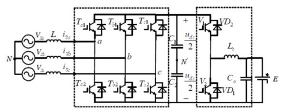
Fig. 1 Topology of an efficient high power factor charger
It consists of a three-phase voltage source PWM rectifier in the front stage and a current reversible chopper circuit in the rear stage. The Current Reversible Chopper DC / DC circuit of the later stage can be understood as a composite circuit composed of a boost circuit and a buck circuit. The circuit can not only realize the forward flow of the circuit, but also realize the reverse flow of current, so as to realize the two-way flow of the energy of the whole charger.
Due to the non-isolated DC / DC topology, the high-frequency transformer is removed, the conversion efficiency is improved, and the system cost and loss are reduced. However, one situation we have to consider is the leakage problem of the whole system. As a complex power electronic device, the leakage problem of two-way high-power charger is difficult to avoid. It is necessary to limit the leakage to a certain range through good control strategy in the design. Otherwise, there are risks for the power grid, the device itself or the safety of life and property. At the same time, it is also necessary to adopt a basic protection means to prevent the harm of leakage when the leakage exceeds the expectation.
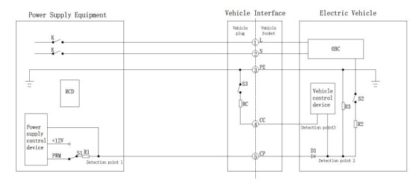
Fig. 2 On board motor input control pilot circuit
The above fig.2 is intercepted in QC / T 895-2011 conductive on-board charger for electric vehicles, which reflects the general model of the connection between the power grid and the charger. The on-board charger supplies power to the on-board charger of electric vehicles through the charging cable. The on-board charger converts the connected AC into DC to charge the storage battery. When feeding to the power grid, the battery converts DC into AC through the on-board charger and feeds back to the power grid through the charging cable. A leakage current protector is installed inside the power supply equipment (charging pile) to protect the whole power grid and the energy exchange process of electric vehicles. The leakage current protector is also known as residual current protector (RCD). RCD is the basic protection means, so its reliability is very important.
As we all know, the power supply system has three-phase three wire system and three-phase four wire system. The International Electrote-chnical Commision (IEC) stipulates TT system, TN system and it system. When using this two-way high-power charger, the limitation of DC / DC isolation transformer is lost, and the battery is the first to gain freedom, which is no longer isolated from the system. Therefore, during the long-term use of the battery, if the DC bus has insulation failure, the leakage will be fed back to the AC side through the body grounding PE line. Taking the positive leakage of battery DC bus as an example, the leakage model is shown in the fig.3 as below.
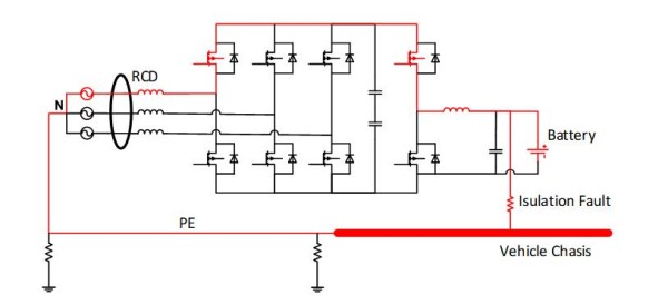
Fig. 3 Leakage model of battery positive short circuit to ground
As we can see that the positive leakage of the battery DC bus is fed back to the AC side to form a circuit. This unexpected DC current will affect the whole system. If we simulate the equivalent circuit, we will find that the whole charging current is distorted, resulting in the reduction of charging efficiency and even the service life of the battery. More seriously, if the PE line is disconnected and the grounding wire is missing, this part of the current may pass through the human body and cause harm to the human body. If the DC current enters the power grid, the consequences will be unimaginable and will harm the whole distribution network. Therefore, when DC leakage occurs, the circuit must be disconnected, the device must be checked, and the function of detecting leakage and disconnecting the circuit is naturally completed by the residual current protector (RCD).
In the IEC 61851-1-2017, the protection requirements for residual current are: each AC connection point shall be separately protected by residual current equipment (RCD), the RCD protecting each connection point shall at least meet the requirements of type a RCD, and its rated residual working current shall not exceed 30mA. When the EV charging point contains a socket or vehicle connector conforming to IEC 62196, additional protection measures need to be taken for smooth DC fault current. The leakage current protection for it should be at least type B or type A, and can be separated when the current exceeding 6mA / DC is detected.
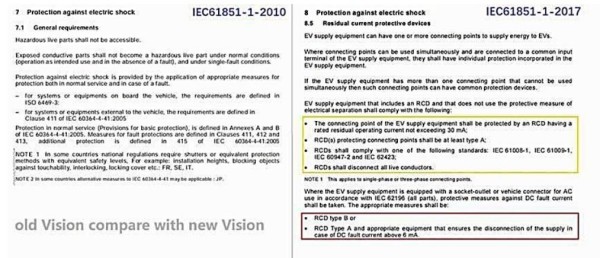
Fig.4 The old Vision compared with the new Vision of IEC 61851-1
To understand why to detect smooth DC 6mA, we need to start from standard and safety. The essence of leakage current protection of charging pile is introduced in iec61851 standard, namely “protection against electric shock”. Neither domestic safety standards nor foreign safety standards set smooth DC 6mA as human body safety protection current, because such a small current would not cause harm to human body. The reason for detecting it is also very simple. The excessive existence of smooth DC component will lead to the early saturation of type a magnetic ring, and finally lead to the inaccurate detection of AC Leakage by type a leakage protection.
Resistance requirements of different leakage protection to smooth DC leakage in international specifications:
1) Type AC: it cannot be detected in the environment with smooth DC leakage
2) Type A: it can only work in the environment with smooth DC leakage less than 6mA
3) Type F: it can only work in the environment with smooth DC leakage less than 10mA
4) Type B: sensitive to smooth DC leakage
Conclusion: The purpose of detecting smooth DC 6mA is to ensure the accuracy of type a leakage protection.
Therefore, it is very necessary to detect and protect the smooth DC 6mA based on the theoretical inspection of type A, because the leakage protection of type A is not designed for the scene of AC pile, and excessive smooth DC components can lead to the blindness of type a leakage protection. So it is need to patch this detection to the bug.
Type B is already a complete comprehensive coverage leakage protection measure. It is sensitive to smooth DC leakage and does not need to be patched. If it is added, it will increase the misoperation probability of leakage protection during electric vehicle charging because the protection value of smooth DC 6mA is really very small.
In the process of realizing V2G of electric vehicle, we need to consider how to realize integration and miniaturization, and also take into account all components of the whole system. Observing the current situation and future development direction of the field of electric vehicles, from the perspective of leakage protection, we urgently need to upgrade the current type a residual current protector to type B, which is a responsible practice for the whole industry.
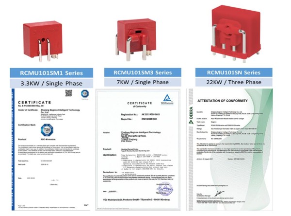
Magtron – All type Current Sensitive Residual Current monitoring Unit (RCMU Series Sensor) developed for EV-Charging Providing all-current sensitivity.
• Benefits:
- Protects against hazardous situations with fault currents, Preserving RCCB type A from saturation in case a smooth DC component in the circuit
- Small volume and footprint for integration into compact IC-CPD and AC Charging Wall-box Charging Piles and OBC (On board Charging)
- Robust mechanical and electrical design suitable for harsh environmental conditions
- Electrical safety at low cost (compared to TYPE B RCCB)
- Integrated self-check functions
• Applications (EV Charging Mode 2 Mode 3 and OBC)
- IC-CPD in charging Cables for electric vehicles (EV) and plug-in hybrid electric vehicles (PHEV).
- AC Charging Wall-box for EV and PHEV.
- AC Charging piles for EV and PHEV
- OBC (On board Charging) system
• Certification
- TUV SUV Mark: B 1135980001
- TUV Rheinland: 505140000001
- DEKRA Attestation Of Conformity: 6097030.01
Media Contact
Company Name: Magtron Intelligent Technology Co.,Ltd
Contact Person: Morgan
Email: Send Email
Phone: +86-573-82660100
Country: China
Website: www.magtronworld.com
