CNC (Computer Numerical Control) machining is a standard manufacturing and prototyping process used in the production of metal and plastic products. This subtractive manufacturing method focuses on a raw material block exposed to a machining controlled material-removal process in consecutive phases while employing cutting tools until the desired part’s final shape is achieved.
Machining is a technology that enables the production of high-quality components (compared to 3D printing). Practically any material, both metallic (aluminum or magnesium alloys, steels) and plastic may be machined (such as ABS, Nylon, Delrin, etc.). Even though much geometry may be programmed manually, Prototool always requires a 3D CAD file to program the CNC machines using CAM software, ensuring precision and avoiding any mistakes in drawings or versions.

Process
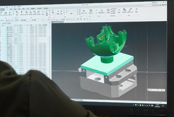
Beginning with the 3D file, the file of the component to be created is processed by CAM (computer-aided manufacturing) software, which determines the tool paths to be manufactured based on the geometry of the part.
A machine code is formed from the virtual tool paths collected by the CAM software, which indicates to the machine’s control panel all of the characteristics and conditions necessary to build the part: tool rotation speed, spindle feed speed, depth of each pass, kind of tool, and so on.
In general, most components require the involvement of many tools, each with its unique characteristics, which are employed sequentially in different machining phases until the final shape is obtained.
Types of Machinery
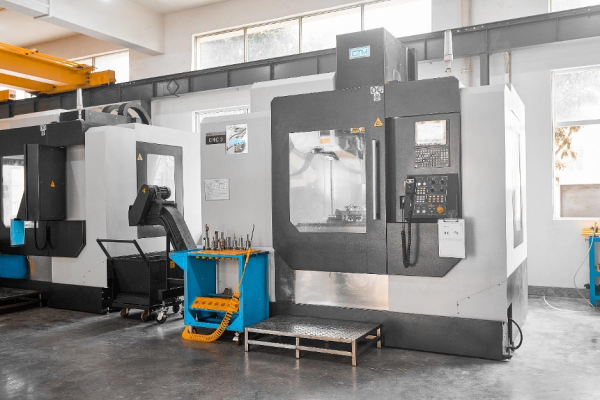
Among other things, machining machinery is characterized by the number of axes with which it can operate, which is commonly three, four, or five. There are machines with several working axes or various configurations, as well as laser cutting, waterjet cutting, and EDM machines. This guide, on the other hand, focuses on CNC machines that use cutting tools.

CNC Milling 3 Axis
CNC milling machines and CNC turning machines are the most prevalent 3-axis CNC machinery.
The cutting tool on this machine may move in three linear axes, X, Y, and Z (and/or in between interpolations), in line with the workpiece.
The block of material is static in milling machines, while the tools rotate to accomplish cutting speed and material removal.
The resultant geometry of a milled component can be any shape and should not be limited to revolution pieces, as is the case with turning machines.
The first three axes allow the tool and material relative movement on an X, Y, and Z coordinate axis. This is the most popular and widely used type of milling machine.
CNC Milling 4 Axis
An electromechanical module with a 4th axis can be installed into the CNC milling machine to offer the machining center an extra degree of rotation when placing a part concerning its axial axis.
This process is often carried out by adding this 4th-axis module to a standard 3-axis machine.
CNC Milling 5 Axis
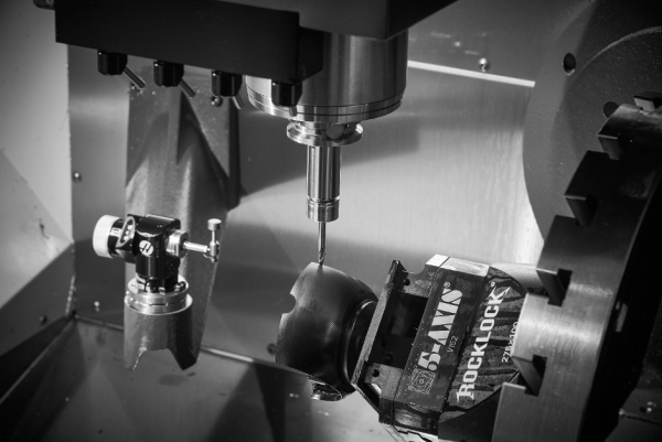
The 5-axis CNC machining centers include either a motorized bed or the spindle itself has two more degrees of flexibility in addition to the initial three axes.

5-axis machines are often more adaptable throughout the machining process, but their acquisition cost is significantly greater, hence the components manufactured on this type of machine are generally more expensive.
CNC Turning 3 Axis
The turning machine’s visible characteristic is that the raw material turns on itself in the spindle and the tools hit on it, forming the machining removal routes. The end product is a “turned” portion.
Turned parts are often more cost-effective than milled ones since the process is faster and easier to automate. As a result, turning is a procedure that allows for great production rates at a cheap cost.
CNC Turning 4 Axis
There is a piece of machinery that allows some of the traditionally fixed tools in the turret to integrate motorization as well as Y displacement.
An extra axis can be added to the turning machine with this specific machine structure, allowing certain geometries to be formed on the component that would otherwise have to be carried out in a procedure after turning (keyways, radial drills, etc.).
Media Contact
Company Name: Prototool Manufacturing Limited
Contact Person: Ray Liu
Email: Send Email
Country: China
Website: https://prototool.com/
